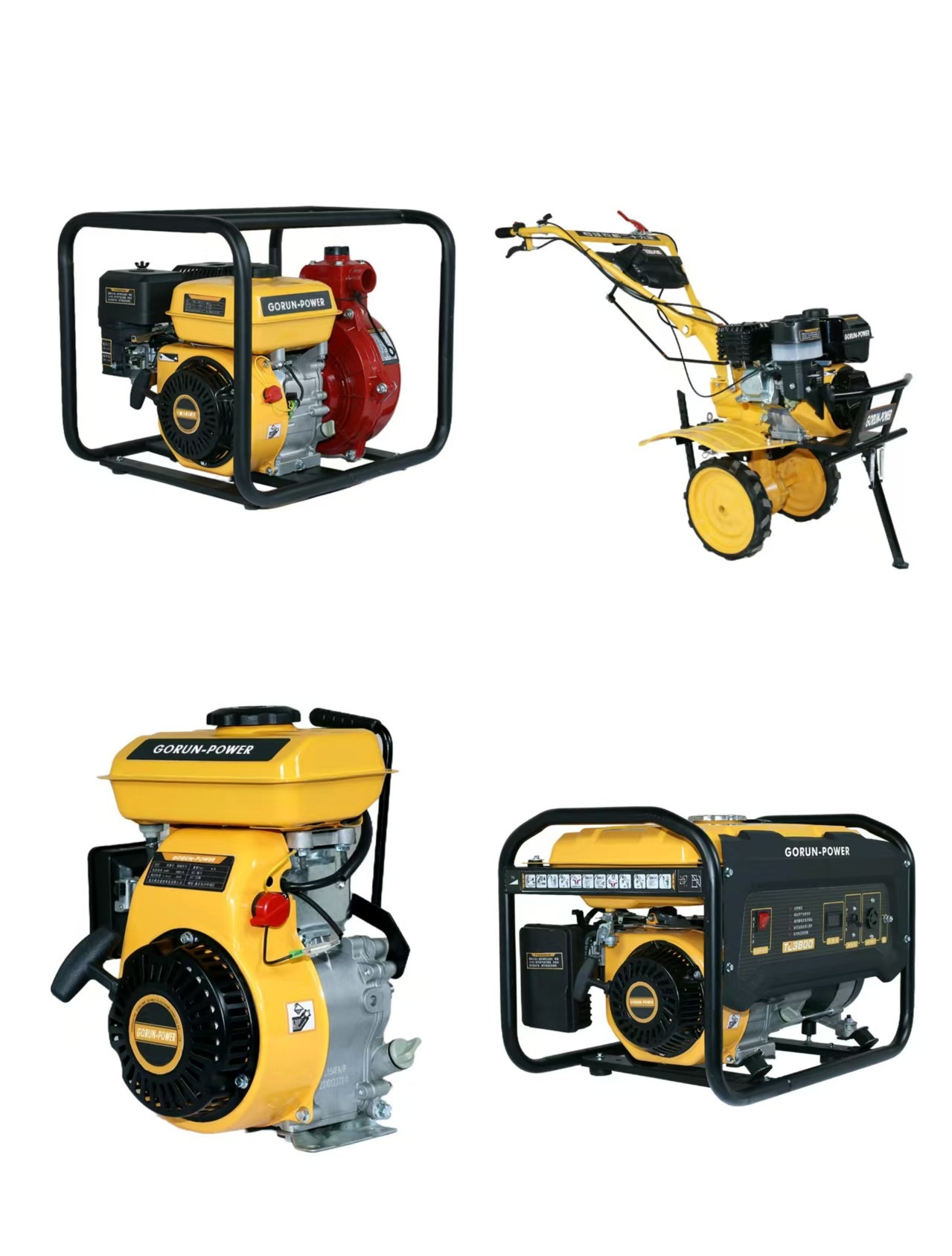
How a 10kW or Below Generator Works: Core Operating Principles
10kW or below generators (for home and light industrial use) convert mechanical energy into electrical energy via electromagnetic induction—the core principle that powers all such units. Below is a concise breakdown of their operating principles, focusing only on how they generate and deliver electricity.
1. Core Scientific Principle: Electromagnetic Induction
All 10kW generators rely on this foundational process:
When a conductor (e.g., copper wire) moves relative to a magnetic field, an electric current is induced in the conductor. For generators, this “motion” comes from a spinning magnetic component (rotor) interacting with a fixed wire component (stator)—the combination that produces usable AC power.
1.1 Key Rules for Power Generation
Three critical rules govern how induction translates to electricity in 10kW generators:
1. Relative Motion Is Required: Current only forms if the magnetic field and conductor move against each other. In 10kW units, the rotor (magnetic component) spins, while the stator (wire component) stays fixed—this efficient design avoids moving heavy wire coils.
2. Voltage Depends on Speed and Coil Turns: The voltage induced in the stator increases with:
- Faster rotor spin (matched to engine RPM, e.g., 3,600 RPM for 60 Hz power in the US, 3,000 RPM for 50 Hz in Europe).
- More wire turns in the stator (10kW models use a moderate number of turns to balance power output and compact size).
3. Current Direction Reverses (AC Output): As the rotor spins, its magnetic poles (north/south) alternate near the stator coils. This reverses the direction of the induced current—creating alternating current (AC), which is compatible with home appliances (fridges, TVs) and small industrial tools (drills, compressors).
2. Key Components & Their Role in Power Generation
10kW generators use 6 core components, each critical to converting mechanical energy to electricity. Their functions are tied directly to electromagnetic induction:
2.1 Stator: Captures Induced Voltage
- Design: Fixed outer component with insulated copper wire coils (1 set for home single-phase 120V/240V power; 3 sets for small industrial three-phase 208V power) wrapped around thin iron “laminations” (reduces wasteful heat from electrical resistance).
- Role: When the rotor’s magnetic field spins past the stator coils, it cuts through the wire—inducing an AC voltage in the coils (per electromagnetic induction). The stator acts as the “collector” of this voltage, which is then sent to external devices.
2.2 Rotor: Creates the Spinning Magnetic Field
- Design: Inner moving component, two common types for 10kW generators:
Permanent Magnet Rotor (smaller 2–5kW models): Compact neodymium/ferrite magnet with fixed north/south poles.
Electromagnet Rotor (larger 7–10kW models): Wire coil around an iron core, powered by a small “excitation current” (from a battery or stator-derived signal).
- Role: Spins via the generator’s engine (mechanical energy input), creating a rotating magnetic field. This moving field is what induces voltage in the stator—no rotor spin = no magnetic motion = no electricity.
2.3 Prime Mover: Provides Mechanical Energy for Rotor Spin
- Design: Small engine (gasoline, diesel, or propane) matched to 10kW output.
- Role: Converts fuel energy into rotational mechanical energy to spin the rotor. For 10kW units:
Gasoline engines: Spin rotors at 3,600 RPM (portable models).
Diesel/propane engines: Maintain steady 3,000–3,600 RPM (stationary models).
- Critical Link: Without the prime mover’s mechanical input, the rotor can’t spin—breaking the electromagnetic induction cycle.
2.4 Slip Rings: Transmit AC Power to External Devices
- Design: Two continuous copper rings attached to the rotor; carbon “brushes” (fixed to the generator frame) press against the rings.
- Role: The stator’s induced AC current flows to the slip rings. The brushes collect this current and send it to the control panel—then to your appliances/tools. Unlike DC generators (which use commutators), slip rings let AC flow directly, avoiding extra components and maintenance.
2.5 Voltage Regulator: Stabilize Induced Voltage
- Design: Small electronic component connected to the rotor (electromagnet type) or engine (permanent magnet type).
- Role: Maintains output voltage at 120V/240V (home) or 208V (industrial)—critical for protecting devices from damage. How it works:
If voltage is too high (e.g., engine speeds up), it reduces the rotor’s excitation current (weakens the magnetic field, lowering stator voltage).
If voltage is too low (e.g., more devices are plugged in), it increases excitation current (strengthens the magnetic field, boosting stator voltage).
- For Permanent Magnet Rotors: Adjusts engine RPM instead (slows down if voltage is high, speeds up if low).
2.6 Cooling System: Protect Induction Components
- Design: Air-cooled (portable models: fan blows air over stator/engine) or liquid-cooled (stationary models: coolant circulates through engine/stator).
- Role: Electromagnetic induction and current flow generate heat (from wire resistance and friction). Overheating damages the stator’s wire insulation or seizes the rotor—so the cooling system keeps components at safe temperatures, ensuring consistent induction and power output.
3. Step-by-Step Power Generation Process
Here’s how 10kW generators convert mechanical energy to usable electricity, step-by-step:
Step 1: Prime Mover Starts & Spins the Rotor
- The engine (gasoline/diesel/propane) activates (manual start: recoil cord/electric button; automatic start: ATS signal for home backups).
- Engine combustion pushes pistons, turning the crankshaft—connected directly to the rotor. The rotor begins spinning at the required RPM (3,000–3,600).
Step 2: Rotor Creates a Rotating Magnetic Field
- Permanent Magnet Rotor: Its fixed north/south poles spin, creating a moving magnetic field around the stator.
- Electromagnet Rotor: The voltage regulator sends excitation current to the rotor’s coil, magnetizing it. As it spins, this creates a rotating magnetic field.
Step 3: Electromagnetic Induction Induces Voltage in the Stator
- The rotor’s moving magnetic field cuts through the stator’s copper coils. This changes the “magnetic flux” (lines of force through the wire)—inducing an AC voltage in the stator coils (per electromagnetic induction).
- For home models: Stator produces 120V/240V single-phase AC; for industrial models: 208V three-phase AC.
Step 4: Slip Rings & Brushes Transfer Power
- The stator’s AC voltage flows to the slip rings (attached to the rotor).
- Carbon brushes (fixed) press against the spinning slip rings, collecting the AC current and sending it to the generator’s control panel.
Step 5: Voltage Regulator Stabilizes Output
- The regulator monitors the current from the brushes. If voltage deviates from 120V/240V/208V, it adjusts the rotor’s excitation current (or engine RPM) to correct it—ensuring stable power for devices.
Step 6: Power Is Delivered to Appliances/Tools
- From the control panel, stabilized AC power flows to outlets:
Home use: Connected to the electrical panel (via ATS, if backup) to power fridges, lights, TVs.
Industrial use: Directly to tools (drills, small compressors) via industrial outlets.
Step 7: Process Stops When Mechanical Input Ends
- Engine shuts off (manual stop: button; automatic stop: ATS detects grid power).
- Rotor stops spinning, the magnetic field stops moving, and induction ceases—no more voltage is produced.
4. Key FAQs About Operating Principles
Q1: Why do 10kW generators produce AC instead of DC?
AC is naturally induced by the rotating magnetic field (rotor spins, poles alternate near the stator—reversing current direction). DC would require a commutator (to “flip” current), adding complexity and maintenance. AC is also compatible with most home/industrial devices, so no extra conversion is needed.
Q2: What’s the link between RPM and frequency?
Frequency (Hz: cycles of AC current per second) depends on rotor RPM and number of rotor poles. For 10kW generators (2-pole rotors):
• 3,600 RPM = 60 Hz (US/Canada).
• 3,000 RPM = 50 Hz (Europe/Asia).
This match to grid frequency ensures devices work normally (e.g., a 60 Hz fridge won’t overheat on 60 Hz generator power).
Q3: Why does grounding matter for induction safety?
If a stator wire frays and touches the generator’s metal frame, the frame becomes “live” (carries current). Grounding (connecting the frame to earth) provides a low-resistance path for this current—preventing electric shock. It doesn’t affect induction but protects users while the generator operates.
Q4: What’s the difference between “running watts” and “starting watts” (related to induction)?
• Running watts: Power needed to keep devices on (matches the stator’s steady induction output).
• Starting watts: Extra power for motor-driven devices (e.g., fridges), which temporarily draw more current. The stator’s induction can handle this briefly (10kW generators have 12–15kW starting capacity) because the voltage regulator boosts the rotor’s magnetic field for a short time.
5. Conclusion
10kW or below generators rely on a simple, efficient cycle: mechanical energy (engine) spins a rotor (creates moving magnetic field) → electromagnetic induction induces AC voltage in the stator → slip rings/regulator deliver stable power to devices. Every component and step ties back to this core principle—no extra complexity, just reliable electricity for homes and small industrial spaces.
Last : Why Cant My Generator Power an Air Conditioner? You Might Be Overlooking These Key Factors
Message


Work Time : 9:00-18:00